Bending Moment at Roller Support
The angle subtended at the centre of the arc AOB is θ and is the change in. At the wall of a cantilever beam the bending moment equals the moment reaction.
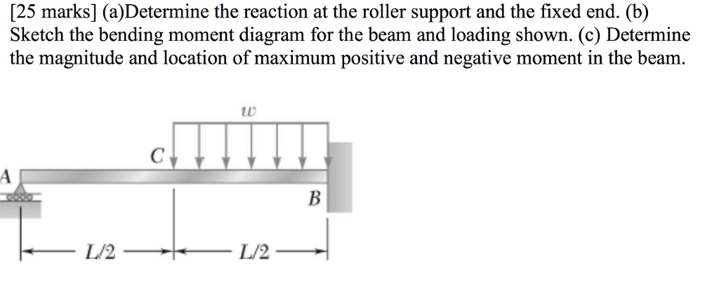
Solved A Determine The Reaction At The Roller Support And Chegg Com
The following movies illustrate the implications of the type of support condition on the deflection behavior and on the location of maximum bending stresses of a beam supported at its ends.
. A simply supported beam cannot have any translational displacements at its support points but no restriction is placed on rotations at the supports. Three-point bending test Figure 54 has been done for a sample arch wire developed above with a fiber volume fraction of 45As of early 2000s there is no specific standard for the characterization of an arch wire. Where E Stiffness in flexure in pounds per square inch.
Fixed End Moments FEM Assume that each span of continuous beam to be fully restrained against rotation then fixed-end moments at the ends its members are computed. Its clear in the first figure that that when one end is fixed while the another end is pinned then the fixed end moment is 3PL 16. Also add moment loads-Add uniform or linearly varying distributed loads at any angle to a member-Add internal pin connections to any member-Calculates internal forces due to support displacements.
Modified K For hinge and roller ends multiply K by 34 to eliminate further distribution of moment on that support. Theory 21 Basis We consider a length of beam AB in its undeformed and deformed state as shown on the next page. The bending moment varies linearly from one end where it is 0 and the center where its absolute value is PL 4 is where the risk of rupture is the most important.
A List four different methods that could be used to determine the reactions for the statically. Secondly drawing a rough sketch of the expected deflected shape of the structure proves quite helpful because the methodology uses the the geometric relationships between slopes and deflections that are specific to the. In real life the roller support example can be a rubber bearing for a flyover.
The moment area theorems rely on the bending moment diagram so at first this should have been determined. The bending moment varies over the height of the cross section according to the flexure formula below. The redundants and calculating the moments.
Push a little further to get a hip flexor stretch as well. It is a rare moment of belonging in a year of rootlessness. Fig1 Formulas for Design of Simply Supported Beam having.
If youre using a roller roll the device up and down along the muscles beside your spine. A simply supported beam is the most simple arrangement of the structure. At the free end the bending moment is zero.
This beam carry load over the span which undergoes both shear stress and bending moment. The bending moment at any location along the beam can then be used to calculate the bending stress over the beams cross section at that location. It beam type undergoes both shear stress and bending moment.
Now if we look at simply supported beams a common configuration is one with a point load at distance a from the first support. This support allow to horizontal movement of beam. Simple Beams that are hinged on the left and fixed on the right.
A simple support pin or roller is equivalent to a point force on the beam which is adjusted in such a way as to fix the position of the beam at that point. One end of the beam is supported by hinge support and other one by roller support. Rental price 70 per night.
Taber Stiffness Units are defined as the bending moment of 15 of a gram applied to a 1 12 wide specimen at a 5 centimeter test length flexing it to an angle of 15. But for the span BC we could see that B is the roller and C is the pinned connection theres no fixed support in the span BC. Such a beam is free to rotate and move along the surface on which it rests.
The bending moment M along the length of the beam can be determined from the moment diagram. 1 normal stress that is caused by bending moment and 2 shear stress due to the shear force. -Assign Fixed Hinged and Roller supports.
Move your hips and bend your knees to roll the ball or roller over the sore areas of your lower back. B If P 20 kN and L 6 m draw the SFD and BMD. Once youre ready reach back with your right arm and grab your ankle or toes depending on whats easiest.
GPS coordinates of the accommodation Latitude 43825N BANDOL T2 of 36 m2 for 3 people max in a villa with garden and swimming pool to be shared with the owners 5 mins from the coastal path. Structural Analysis III 3 Dr. A bending moment acting on the cross section of the bar.
Hinge support is another type. For 3-year terms which are renewable. At the ends of a simply supported beam the bending moments are zero.
Simple Beams that are hinged on the left and roller supported on the right. As the sun sets Dasani and her family step out for some air. E 0006832 1w d 3 θ S T.
The beam is supported at each end and the load is distributed along its length. Get an Access Code. Sizes 1045-1095 Rigid Moment Couplings 458-862 Manual English 1 MB Lifelign Gear Couplings 451-110 Catalog English 6 MB Lifelign Gear Couplings - Metric 451-110M Catalog English 4 MB Product Support Contact Rexnord to receive product and service information for Gear Couplings.
A Stiffness Unit is the equivalent of one gram centimeter. Continue leaning heavily into the ball or roller against the wall to apply pressure to the areas. AB is the original unloaded length of the beam and AB is the deflected position of AB when loaded.
A man brushes past them walking along West 127th Street. Roller supports can be added at any angle-Add point loads to any member or node at any angle. Roll on the area that hurts with the ball or roller.
Simply Supported Intermediate Load. In other words beams with one end pinned and the other end on a roller. At the location where the shear force crosses the zero axis the corresponding bending moment has a maximum value.
However the span size was chosen according to the distance of two adjacent brackets fixed on the teeth Figure 48This size is usually 14 mm Toyoizumi et. To obtain numerical values of diagrams and support reactions you must Get an access code. Why the Fixed End Moment FEM for BC is 3PL 16.
Studying this diagram carefully we note. A Calculate the shear force and bending moment for the beam subjected to a concentrated load as shown in the figure. Bending Moment Diagram BMD Shear Force Diagram SFD Axial Force Diagram AFD Moment is positive when tension at the.
Using the Moment Area Theorems. The internal forces give rise to two kinds of stresses on a transverse section of a beam. Trusses bridges and other structure member.
Roller support mean you are giving beam the ability to resist vertical forces only. Hold the position for 30 seconds keeping your body steady. Adjunct membership is for researchers employed by other institutions who collaborate with IDM Members to the extent that some of their own staff andor postgraduate students may work within the IDM.
Equation Diagram Bending moment diagram of Simply Supported. Determine the reactions and draw the shear and bending moment diagrams for the structures shown A. Carefully drop your right knee to the floor and take a moment to find your balance.
The shear force and the bending moment usually vary continuously along the length of the beam. Then draw the shear force diagram SFD and bending moment diagram BMD.
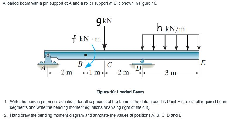
Solved A Loaded Beam With A Pin Support At A And A Roller Chegg Com
Mechanical Engineering Is Bending Moment On Roller Supports At Beams Zero Engineering Stack Exchange

Three Member Frame Pin Roller Side Top Bending Moment
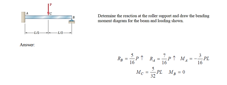
Solved Determine The Reaction At The Roller Support And Draw Chegg Com
No comments for "Bending Moment at Roller Support"
Post a Comment